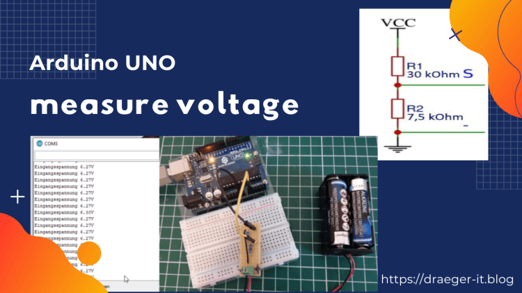
In this post, I want to show how to measure the voltage up to 5V with an Arduino.
Review
In the article Arduino Lektion 4: LED mit Fotowiderstand I showed how to read the value of a photoresistor and “visualize” it via a light emitting diode. What we actually did is to measure the voltage that the photoresistor lets through and then map this value to a PWM signal.
Alternatively, we can also build a small circuit with a rotary potentiometer, in which we can connect the voltage of 5V (which the Arduino supplies via pin 5V) and change it manually with a screwdriver.
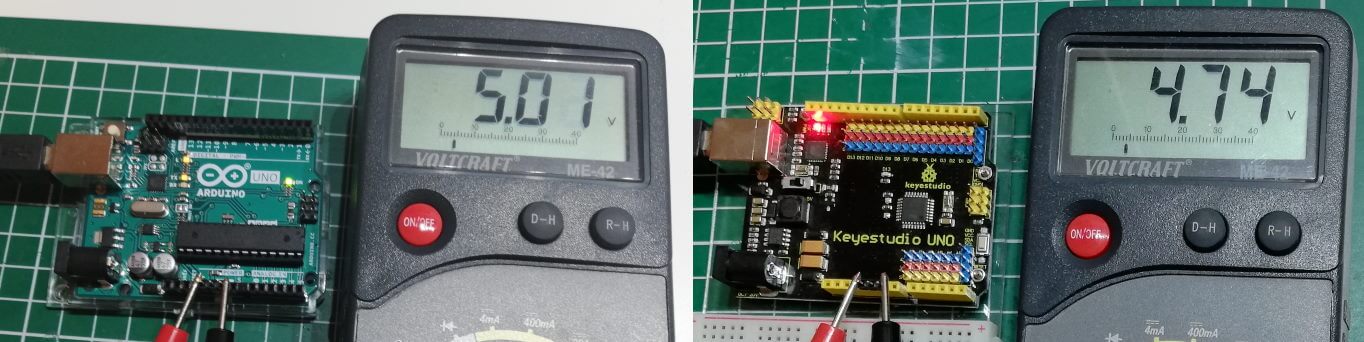
Depending on the quality of the microcontroller, the value can be slightly below or above the value of 5V. However, if you don’t use a clone but an original Arduino UNO, it will deliver almost exactly 5V.
Sample code
In the following sketch I read the value from analog pin A0 and map it first to the possible PWM signal (0..255) and then to a value between 0 and 50 for calculating the voltage.
I deliberately choose the values from 0 to 50 here, so that I can later divide this by 10 and thus get a floating point value.
#define rotaryResistor A0
#define led 9
void setup() {
   Serial.begin(9600);
   pinMode(rotaryResistor, INPUT);
   pinMode(led, OUTPUT);
}
void loop() {
   int resistorValue = analogRead(rotaryResistor);
   int ledValue = map(resistorValue, 0, 1023, 0, 255);
   analogWrite(led, ledValue);
   double v = map(resistorValue,0,1023,0,50);
   Serial.print(v/10, 2);
   Serial.println("V");
   delay(100);
}
measure voltages greater than 5V
If you want to measure voltages higher than 5V, you have to use a voltage divider circuit.
In the following I show you the circuit diagram, if the input voltage “VCC” is up to 25V.
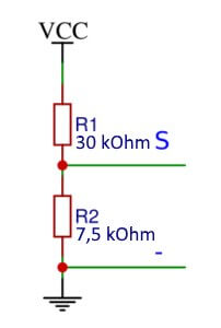
In this case a voltage of maximum 5V is output at “S” & “-“, which we can then measure again with our Arduino at the analog input.
Building the circuit with a breadboard
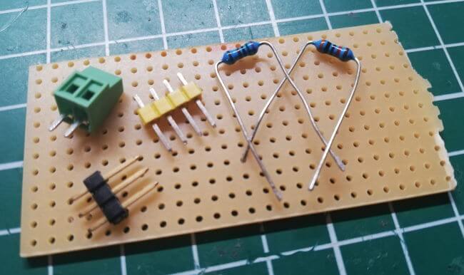
Components needed for the circuit
First we want to build the circuit on a breadboard. This has the advantage that we could still make a few modifications.
- 1x Breadboard* with min. 170 Pins,
- 4x Breadboard wires*, 10 cm, male – male,
- 1x 30 kOhm, Resistor*,
- 1x 7,5kOhm, Resistor*,
- eine 9V Battery*
Note from me: The links marked with an asterisk (*) are affiliate links. If you make a purchase through these links, I will receive a small commission to help support this blog. The price for you remains unchanged. Thank you for your support!
Layout
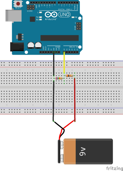
Structure of the circuit on a breadboard
Components needed for the circuit
After we have created and tested the circuit on the breadboard in the first step, we want to “perpetuate” it is on a breadboard. For this purpose, we need an additional small breadboard.
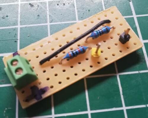
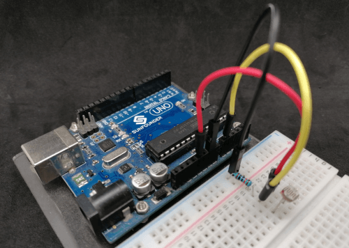
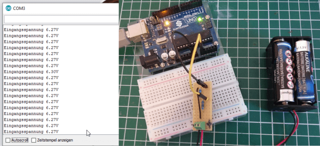
If you now connect the finished board to the Arduino UNO (yellow > analog pin A0, black > GND) you can see the voltage on the serial monitor of the Arduino IDE.
With this circuit, as already mentioned, voltages up to a maximum of 25V are possible!
Alternative, a ready sensor
Of course, it is easier with a ready-made voltage sensor.
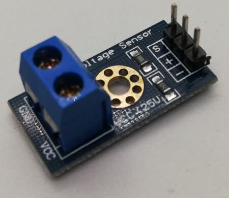
I have already presented this sensor in the article Arduino Lektion 54: Spannungssensor.
And if I am to be completely honest, I have taken the circuit from exactly this sensor and rebuilt.
The sensor costs at ebay.de just under €4 incl. shipping costs (This time it is even, no matter whether you have the goods delivered from China or Germany.).
Letzte Aktualisierung am: 10. March 2024