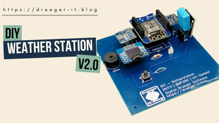
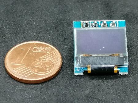
In this article I would like to introduce you to the DIY Weather Station V2. This slightly improved version now has an OLED display and a piezo buzzer for the output of signals.
History – What is the difference to version 1?
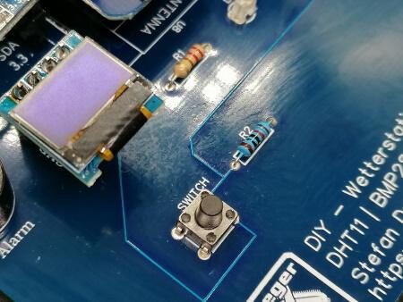
In the first version, I had chosen the design of the board to be quite small and compact. This resulted in a round circuit board that was reduced to the essentials. However, it lacked a display on which the values could also be shown. In addition, a small button for print mounting (12 mm high) was added, which can be used to step through the various sensor values.
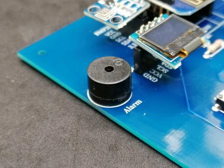
Furthermore, a small piezo buzzer was missing, which serves to acoustically signal a previously programmed threshold value.
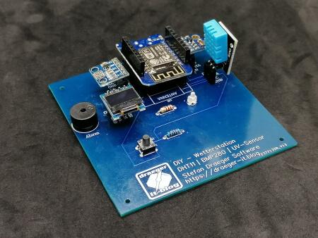
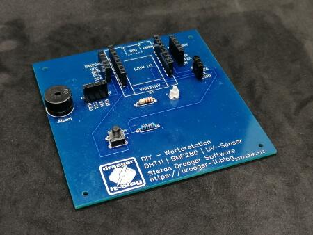
Structure of the circuit board
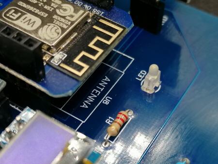
The installed sensors / actuators are connected via socket connectors. This not only makes it easy to replace sensors, but also allows the sensors to be installed anywhere.
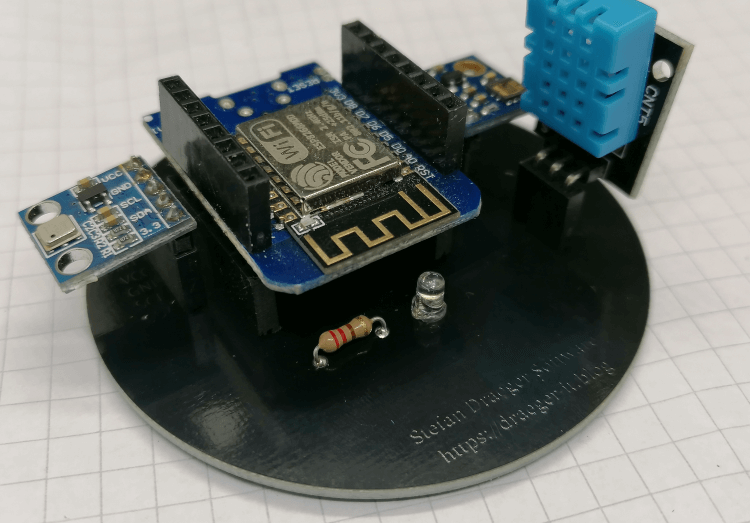
Sensors & actuators at a glance
The DIY weather station has 3 sensors, an OLED display and a piezo buzzer (and also a print button and a light-emitting diode).
The following values can be measured with the installed sensors:
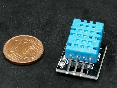
- DHT11
- Temperature
- rel. Humidity
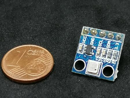
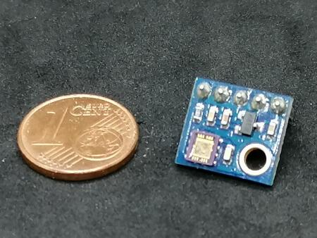
- BMP180
- Air pressure
- Temperature
- UV Sensor
- UV-A & UV-B radiation
The BMP180 & DHT11 sensor both provide a temperature that we can process, so we may have the ability to measure a temperature at two locations and process them in one program.
Programming the DIY Weather Station V2
This small weather station can be programmed in the Arduino IDE with C/C++. It is also possible to program the sensors or microcontrollers in ESPeasy or MicroPython, but more about this in a separate article.
How to set up the Arduino IDE on a Microsoft Windows PC is explained in the article Installing the Arduino IDE. If you have a Linux PC, I would recommend the article Installing the Arduino IDE on Linux.
GitHub Repository
On my GitHub repository StefanDraeger / ESP8266—DIY-Wetterstation you can find a detailed explanation of this project with pictures and source code for small projects you can build with this board.
Program for reading out the sensors
On the GitHub repository mentioned above, you can find small examples of the sensors as well as two projects that show the sensor data on the OLED display on the one hand and on a website on the other.
Show sensor data on the OLED display
Display sensor data on a web page
Costs
The costs for the entire project amounted to 13 € for the components (sensors, actuators, socket connectors, etc.). Theoretically, you would have to add the time that went into the development of the board in EasyEDA, but I am taking this out of the calculation.
The production costs for the board amount to just under $14.45 (approx. €12.67) including shipping via “Global Direct Line Saver”.
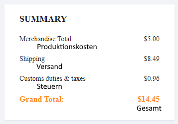
Shipping via “Global Direct Line Saver” is particularly cheap, but the package takes much longer to reach the recipient. If you use JLCPCB.com, you will receive a message after production and can therefore easily calculate how long it will take from production to dispatch (usually only one day).
Letzte Aktualisierung am: 29. April 2023