In this tutorial, I want to show you how to set up and run the ESP32-CAM with a small example.
Buy an ESP32-CAM
The ESP32-CAM for this tutorial I bought via ebay.de for just under €8 incl. shipping costs*.
Note from me: The links marked with an asterisk (*) are affiliate links. If you make a purchase through these links, I will receive a small commission to help support this blog. The price for you remains unchanged. Thank you for your support!
You can get this microcontroller at aliexpress.com or also banggood.com for a much cheaper price, but these portals are not the most reliable and my experience has shown that it is a big gamble whether the parts arrive at all or intact.
To load a sketch on this microcontroller, you also need a FTDI module, this module you can get at ebay.de for just under €4.
Technical data
| Microchip | 32Bit Dual Core CPU with 240 MHz clock speed, computing power up to 600 DMIPS |
| Memory | 520 KB SRAM 4 MB PSRAM |
| Interfaces | Bluetooth / Bluetooth Low Energy (BLE), Wi-Fi (802.11 b/g/n/e/i), UART, SPI, PWM, ADC & DAC |
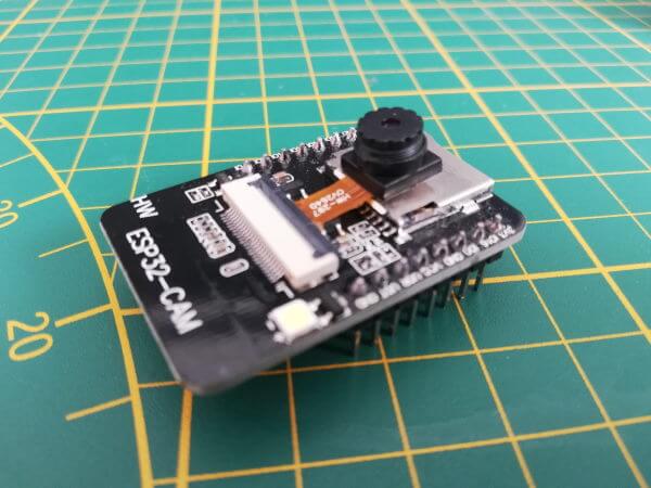
| available Camera modules | OV2640 / OV7670 |
| others | SD-Card slot for up to 4 GB Micro SD-Cards |
| Dimensions (L x B x H) | 40 mm x 27 mm x 18 mm |
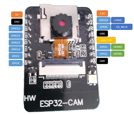
Pin assignment of the ESP32-CAM
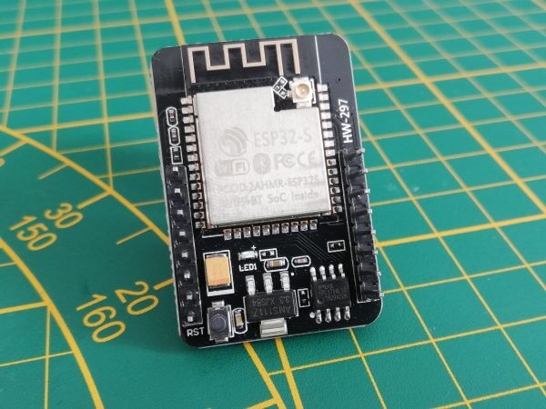
The microcontroller ESP32-CAM has 16 pins of an interface for the camera module and a SD card slot for Micro SD cards up to 4 GB.
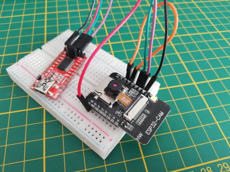
Connection and circuit
As already mentioned, an FTDI module is required.
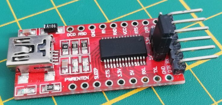
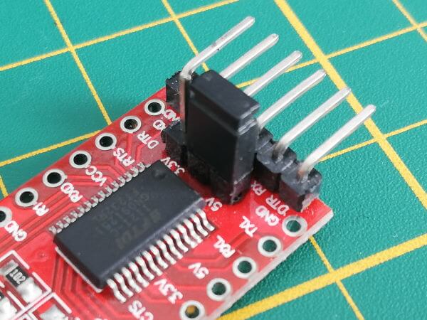
Since we want to operate the ESP32-CAM via 5V, we have to set the jumper on the FTDI module to 5V additionally.
So for the setup we need besides the FTDI module & the ESP32-CAM module 4 breadboard cables (20 cm, female – male) and 1 breadboard cable (10 cm, male – male), and a breadboard with min. 400 pins.
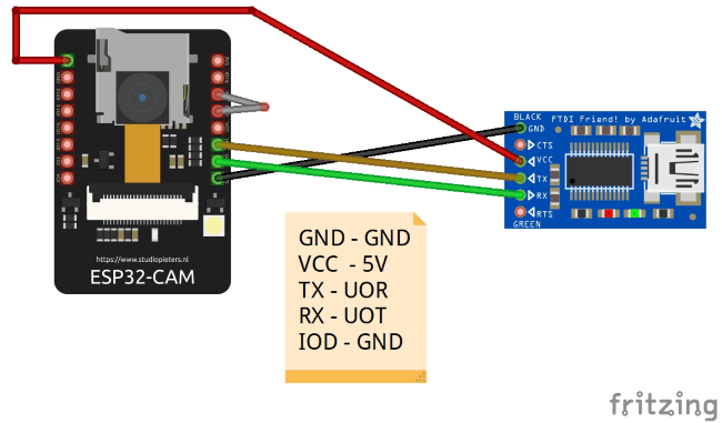
| FTDI Modul | ESP32-CAM |
|---|---|
| RX | UOT |
| TX | UOR |
| GND | GND |
| VCC | 5V |
However, this bridge is only needed for uploading the sketch, for operation it must be removed again.
Programming the ESP32
Setting up the board driver
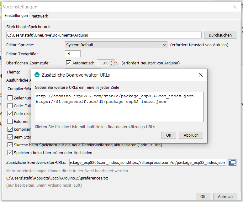
In order to program the ESP32 with the Arduino IDE, a driver for the board must also be installed. This driver is added via the board manager. However, you have to add the address “https://dl.espressif.com/dl/package_esp32_index.json” to the “Board Manager URLs” under the preferences beforehand.
If this is done, the board manager can be opened via “Tools” > “Board: xyz” > “Board manager…”. In the window of the board manager is now searched for the term “esp32” (1), there should be exactly one hit, which we install with the button “Install” (2). After the driver has been installed (this can take some time depending on the internet & computer speed of the computer) we can close this window with the button “Close” (3).
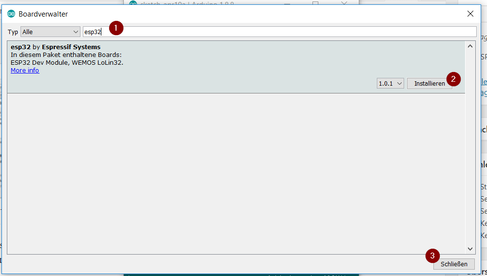
Although I have a 50Mbit line, the download of the approx. 32 MB package took an unusually long time, so please allow a little more time for this process.
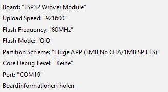
Setting up the board in the Arduino IDE
If you have installed the board driver now, you have to select it and change some default values.
Upload the example from the ESP32 package
The ESP32 package comes with an example for the ESP32 – CAM, if you don’t have it you can download it for free from the GitHub repository espressif/arduino-esp32. Alternatively I offer you a ready configured sketch at the end of this post.
Once you have uploaded this example, you will need to restart it once. This restart can be done either by using the reset button or by removing the power supply and plugging it in again.
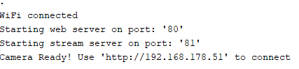
In the serial monitor of the Arduino IDE you can see the following output.
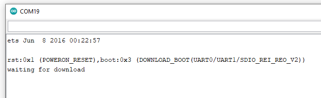
This issue stops a bit longer, which means you have to wait a bit until it continues.
When the process is complete, then the connection to the Wi-Fi network is established and the IP address of the ESP32-CAM module is displayed.
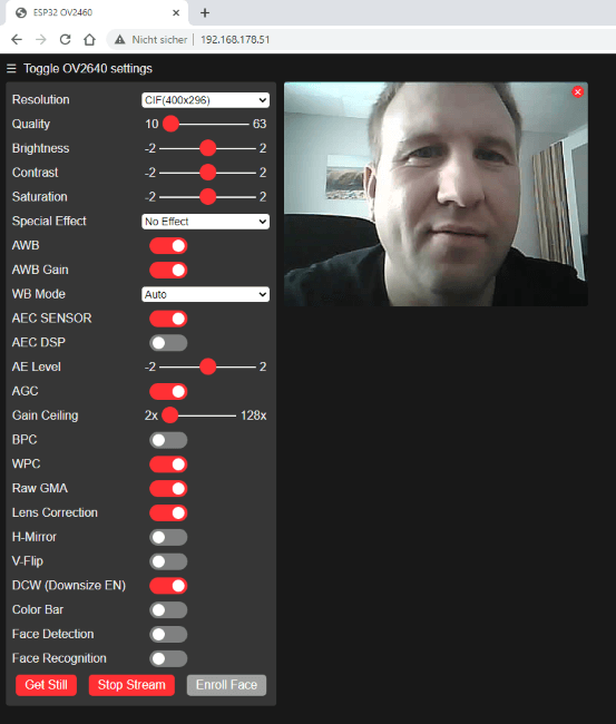
Web page in browser
When the WiFi connection is established, you can use the displayed IP address in the browser to display a page where you can start a stream, for example.
Streaming with VLC player
The free VLC player is a true all-rounder when it comes to playing multimedia files. It can also open and play network streams. I have already presented this for the Raspberry PI Camera B01 and now I would like to show it for this ESP32-CAM.
The address for the stream is http://:81/stream, you can either read the IP address from your router or from the serial monitor of the Arduino IDE.
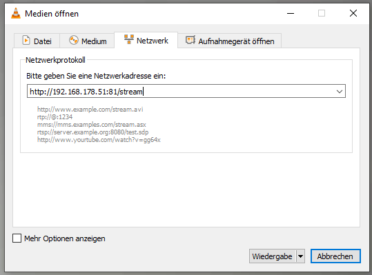
In the VLC Player navigate to the main menu “Media” > “Open Network Stream…” to start the dialog “Open Media”. In this dialog you have to enter the address shown above (of course with your IP address), in my case it is “http://192.168.178.51:81/stream”.
But the network stream in the VLC player can only be started if no other is started (ebsp. via the web page in the browser).
Taking a picture
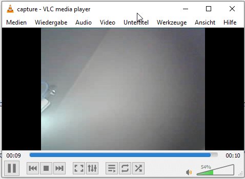
You can also get a single picture from the active ESP32-CAM, just end the address with “/capture” instead of “/stream”. A photo is now taken and displayed for 10 seconds.
Letzte Aktualisierung am: 10. March 2024