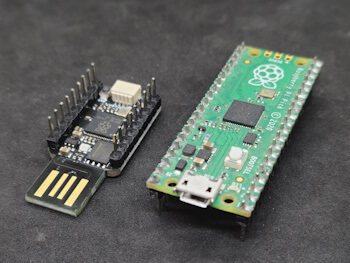
In this article, I would like to introduce you to a compact microcontroller featuring the RP2040 chip, which plugs directly into a USB port, eliminating the need for an additional data cable.

I purchased this microcontroller for approximately €5, including shipping, from AliExpress. In terms of price, it is comparable to the original Raspberry Pi Pico (without WiFi).
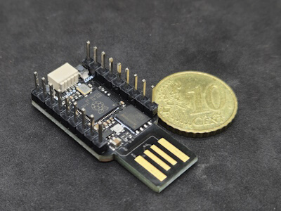
Structure of the RP2040 Microcontroller for the USB Port
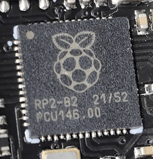
This microcontroller is based on the RP2040 chip with the following specifications:
- Dual ARM Cortex-M0+ @ 133 MHz
- 264 kB SRAM
- 16 MB Flash memory
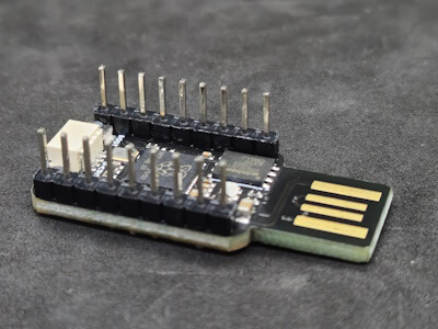
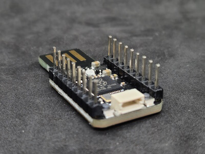
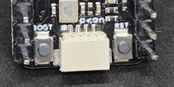
Additionally, it features a programmable RGB LED and a Qwiic interface for connecting I²C sensors and actuators.
There are also two buttons: RESET and BOOT, with the BOOT button used, for example, to flash a different firmware.
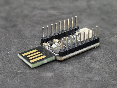
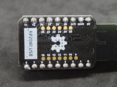
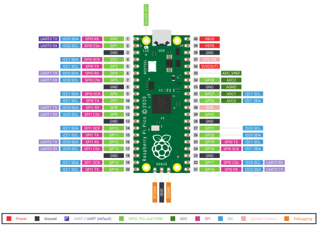
Pinout of the Microcontroller
Due to its compact size, not all pins provided by the RP2040 are accessible on the microcontroller. The available pins are labeled on the back of the device and can be accessed via pin headers or additional solder points.
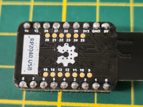
The pinout corresponds to the designations of the original Raspberry Pi Pico, with pins 0 to 29 also present on this mini USB microcontroller.
Comparison with the Original Raspberry Pi Pico
The Raspberry Pi Pico has been on the market for several years and even offers support for WiFi and Bluetooth since 2023. In comparison, the small microcontroller for the USB port fares worse. Despite the nice RGB LED, I consider having many pins available for projects to be more important.
For smaller projects, however, the Mini USB RP2040 is better suited, so the choice of the best microcontroller ultimately depends on the specific application.
Programming the Mini USB RP2040 Development Board in the Arduino IDE
The microcontroller is prepared for programming in the Arduino IDE. After installing the appropriate board driver, you can get started right away.
Installing the Board Driver
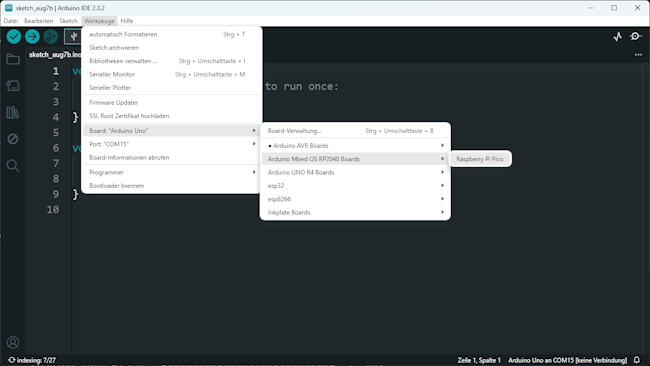
Open the board manager in the Arduino IDE, search for “RP2040,” and install the “Arduino Mbed OS RP2040 Boards” package.
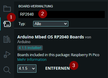
After successful installation, you will find the board under “Tools” > “Board: xyz” > “Arduino Mbed OS RP2040 Boards” > “Raspberry Pi Pico.”
Programming the RGB LED
The RGB LED is connected to GPIO 22 and can be easily programmed with the Adafruit NeoPixel library.
#include <Adafruit_NeoPixel.h>

#define PIN 22 // RGB LED connected to GPIO22
#define NUMPIXELS 1 // Number of built-in RGB LEDs

Adafruit_NeoPixel pixels(NUMPIXELS, PIN, NEO_GRB + NEO_KHZ800);

uint32_t colors[5] = {
  pixels.Color(0, 150, 0),     // green
  pixels.Color(150, 0, 0),     // red
  pixels.Color(0, 0, 150),     // blue
  pixels.Color(150, 150, 0),   // yellow
  pixels.Color(255, 255, 255)  // white
};

void setup() {
  // Start communication with the NeoPixels
  pixels.begin();
}

void loop() {
  // Clear the set color
  pixels.clear();
  // Loop from 0 to 4
  // Since arrays start with index 0, we need to start here
  // and loop up to a maximum of 4.
  for (int i = 0; i < 5; i++) {
    // Set the color from the array with the loop variable i at the
    // index 0 of the LED strip.
    pixels.setPixelColor(0, colors[i]);
    // Display the color
    pixels.show();
    // A short pause of 500 milliseconds
    delay(500);
  }
}
Programming a Flame Sensor
On my blog, I have already introduced the flame sensor for the Arduino. As the name suggests, this sensor reacts to a flame, such as from a lighter. The sensor has two pins (one analog and one digital) and two for power supply.
In the following code, I use the digital output of the sensor, and when it is HIGH, I change the color of the LED from green to red.
#include <Adafruit_NeoPixel.h>

#define PIN 22
#define NUMPIXELS 1

#define flameSensor 0

Adafruit_NeoPixel pixels(NUMPIXELS, PIN, NEO_GRB + NEO_KHZ800);

void setup() {
  Serial.begin(9600);
  pinMode(flameSensor, INPUT_PULLDOWN);
  pixels.begin();
}

void loop() {
  pixels.setPixelColor(0, pixels.Color(0, 150, 0));
  pixels.show();
  if (digitalRead(flameSensor) == 1){
    Serial.println("Flame detected");
    pixels.setPixelColor(0, pixels.Color(150, 0, 0));
    pixels.show();
    delay(500);
  }
}
Outlook on the Microcontroller with RP2040 Chip for the USB Port
In the next article, I would like to present a small project with this mini USB microcontroller, so stay tuned…
Letzte Aktualisierung am: 05. February 2025