After demonstrating how to flash the ESP32 for MicroPython and introducing the programming language’s structure, we will now control LEDs and buttons via GPIO pins.

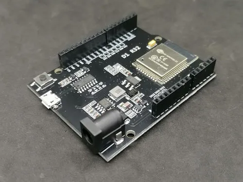
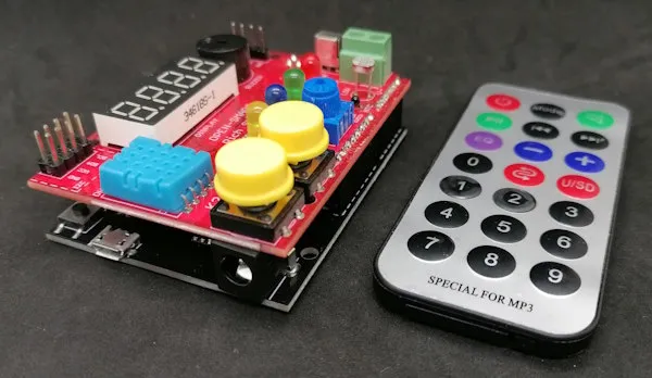
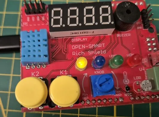
For this series, I am using the ESP32 D1 R32 along with the Rich Shield Two from Open Smart. If you don’t have this shield, I’ll provide guidance on how to set up the circuit on a breadboard.

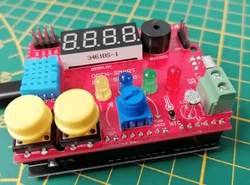
LEDs on the Rich Shield from Open Smart
The LEDs on the Rich Shield from Open Smart are connected to the following pins:
| LED | ESP32 D1 R32 | Arduino UNO R3 |
|---|---|---|
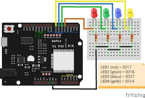
| LED1 (red) | IO17 | D4 |
| LED2 (green) | IO16 | D5 |
| LED3 (blue) | IO27 | D6 |
| LED4 (yellow) | IO14 | D7 |
Circuit without Rich Shield
If you don’t have the Rich Shield from Open Smart, you can build the circuit on a breadboard as shown below:
Controlling the GPIO Pins of the LEDs
A GPIO pin can serve as both input and output. An LED is an output device (in this case, light), so the pin is defined as Pin.OUT. If we had a button, it would be defined as Pin.IN.
To introduce a small delay in the code, we need to import the time module. This module offers many functions, one of which is time.sleep(<seconds>), where the parameter is the number of seconds. (Unlike the Arduino IDE’s delay function, which expects milliseconds.)
# Module for accessing GPIO pins
import machine
# Module for functions like introducing a pause in the code
import time

# Create a variable for GPIO17 as output
led1 = machine.Pin(17, machine.Pin.OUT)
led1.value(1)  # Activate the pin
time.sleep(1)  # Pause for 1 second
led1.value(0)  # Deactivate the pin
When we run the code, LED1 (red) will be activated for 1 second and then deactivated. The program then terminates automatically.
Making the LED Blink
In the post “MicroPython with ESP32: Programming basics” I introduced loops. With a loop, we can now make the LED blink. We can make it blink a specific number of times, for a specific duration, or indefinitely.
Blinking the LED a Specific Number of Times
To blink an LED a certain number of times, we use a for loop to count from/to a specified range. In the code below, I count from 1 to 5, without using the loop variable i.
# Module for accessing GPIO pins
import machine
# Module for functions like introducing a pause in the code
import time

# Pause duration in the loop
pause = 0.250

# Create a variable for GPIO17 as output
led1 = machine.Pin(17, machine.Pin.OUT)

# Loop from 1 to 5
for i in range(1, 6):
    led1.value(1)  # Activate the pin
    time.sleep(pause)  # Pause
    led1.value(0)  # Deactivate the pin
    time.sleep(pause)  # Pause
In the video, you can see the small red 5mm LED blink a total of 5 times. If we adjust the range in the for loop to range(1, 11), it would blink 10 times.
Blinking the LED for a Specific Duration
To make the LEDs blink for a specific duration, we need the current timestamp and the desired duration. Simple mathematics and a while loop help us achieve this.
# Module for accessing GPIO pins
import machine
# Module for functions like introducing a pause in the code
import time

# Pause duration in the loop
pause = 0.250

# Create a variable for GPIO17 as output
led1 = machine.Pin(17, machine.Pin.OUT)

# Current milliseconds since the program started
currentTimestamp = time.ticks_ms()
# Duration for which the LED should blink
duration = 5000

# Blink the LED for a specific duration
# The function ticks_ms() returns the current milliseconds since the program started.
while time.ticks_ms() < (currentTimestamp + duration):
    led1.value(1)  # Activate the pin
    time.sleep(pause)  # Pause
    led1.value(0)  # Deactivate the pin
    time.sleep(pause)  # Pause
In the video, I let the LED blink for 2 seconds; with a pause of 0.25 seconds each, it blinks 4 times.
Making the LED Blink Indefinitely
To make the LED blink indefinitely, we simply set our while loop to an infinite loop by passing True.
# Module for accessing GPIO pins
import machine
# Module for functions like introducing a pause in the code
import time

# Pause duration in the loop
pause = 0.250

# Create a variable for GPIO17 as output
led1 = machine.Pin(17, machine.Pin.OUT)

# Start the infinite loop
while True:
    led1.value(1)  # Activate the pin
    time.sleep(pause)  # Pause
    led1.value(0)  # Deactivate the pin
    time.sleep(pause)  # Pause
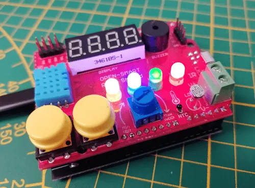
Programming a Running Light
By activating and deactivating the LEDs sequentially, we can create a simple running light effect.
To reduce the amount of code and keep it concise, I create an additional function to set the status of the LEDs.
# Module for accessing GPIO pins
import machine
# Module for accessing functions like introducing a pause
import time

# Pause duration in the loop
pause = 0.130

# Creating variables for the LEDs as outputs
led1 = machine.Pin(17, machine.Pin.OUT)
led2 = machine.Pin(16, machine.Pin.OUT)
led3 = machine.Pin(27, machine.Pin.OUT)
led4 = machine.Pin(14, machine.Pin.OUT)

# Function to set the LED statuses
def ledLightUp(led1Status, led2Status, led3Status, led4Status):
    led1.value(led1Status)
    led2.value(led2Status)
    led3.value(led3Status)
    led4.value(led4Status)
    time.sleep(pause)  # Pause

# Start the infinite loop
while True:
    # Call the ledLightUp function with the new LED status as parameters
    ledLightUp(1, 0, 0, 0)  # Red LED on
    ledLightUp(0, 0, 0, 0)  # All LEDs off
    ledLightUp(0, 1, 0, 0)  # Green LED on
    ledLightUp(0, 0, 0, 0)  # All LEDs off
    ledLightUp(0, 0, 1, 0)  # Blue LED on
    ledLightUp(0, 0, 0, 0)  # All LEDs off
    ledLightUp(0, 0, 0, 1)  # Yellow LED on
    ledLightUp(0, 0, 0, 0)  # All LEDs off
Reading Button States
The small shield includes two additional buttons, which we will use to activate LEDs and start various programs.
| Button | ESP32 D1 R32 | Arduino UNO R3 |
|---|---|---|
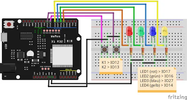
| K1 | IO12 | D8 |
| K2 | IO13 | D9 |
Circuit without Rich Shield
Here’s the circuit setup on a 400-pin breadboard:
Reading the Status of Buttons
To read the button status, we need an infinite loop. Without it, the program wouldn’t be able to evaluate button actions.
# Module for accessing GPIO pins
import machine
# Module for accessing functions like introducing a pause
import time

# Variables for the buttons
k1 = machine.Pin(12, machine.Pin.IN, machine.Pin.PULL_UP)  # Button K1 on GPIO12
k2 = machine.Pin(13, machine.Pin.IN, machine.Pin.PULL_UP)  # Button K2 on GPIO13

# Start the infinite loop
while True:
    # Check if button K1 is pressed
    if not k1.value():
        print("Button K1 pressed!")  # Print to console
        time.sleep(0.25)  # Debounce delay

    # Check if button K2 is pressed
    if not k2.value():
        print("Button K2 pressed!")
        time.sleep(0.25)  # Debounce delay
When pressing one of the buttons, the message “Button K1 pressed!” or “Button K2 pressed!” will appear on the console. A small delay of 0.25 seconds prevents button bouncing.
Activating an LED with a Button
Now, using the knowledge of LEDs and buttons, we can control LEDs with button presses.
# Module for accessing GPIO pins
import machine
# Module for accessing functions like introducing a pause
import time

# Variables for the buttons
k1 = machine.Pin(12, machine.Pin.IN, machine.Pin.PULL_UP)  # Button K1 on GPIO12
k2 = machine.Pin(13, machine.Pin.IN, machine.Pin.PULL_UP)  # Button K2 on GPIO13

# LED1 (red)
led1 = machine.Pin(17, machine.Pin.OUT)

# Start the infinite loop
while True:
    # Activate LED1 when K1 is pressed
    if not k1.value():
        led1.value(1)
        time.sleep(0.25)

    # Deactivate LED1 when K2 is pressed
    if not k2.value():
        led1.value(0)
        time.sleep(0.25)
Toggling an LED with a Single Button
Using a single button, we can both activate and deactivate an LED by checking its current status.
# Module for accessing GPIO pins
import machine
# Module for accessing functions like introducing a pause
import time

# Variables for the buttons
k1 = machine.Pin(12, machine.Pin.IN, machine.Pin.PULL_UP)  # Button K1 on GPIO12
k2 = machine.Pin(13, machine.Pin.IN, machine.Pin.PULL_UP)  # Button K2 on GPIO13

# LED1 (red)
led1 = machine.Pin(17, machine.Pin.OUT)
# LED2 (green)
led2 = machine.Pin(16, machine.Pin.OUT)

# Start the infinite loop
while True:
    # Toggle LED1 when K1 is pressed
    if not k1.value():
        if not led1.value():
            led1.value(1)  # Turn on
        else:
            led1.value(0)  # Turn off
        time.sleep(0.25)  # Debounce delay

    # Toggle LED2 when K2 is pressed
    if not k2.value():
        if not led2.value():
            led2.value(1)  # Turn on
        else:
            led2.value(0)  # Turn off
        time.sleep(0.25)  # Debounce delay
Now, we can use the two buttons to control the red and green LEDs.
Conclusion & Outlook
This concludes the small post. In the next article, I’ll show you how to read the analog rotary potentiometer and map the values to the LEDs.
Letzte Aktualisierung am: 23. May 2025