In this post, you’ll learn how to use Pulse Width Modulation (PWM) with the ESP32 D1 R32 and MicroPython. PWM is a versatile technique widely used in many applications, from LED dimming to motor control. With the ESP32 and MicroPython, generating and controlling PWM signals is straightforward.
n a previous post, MicroPython with ESP32: Introduction to the ESP32 D1 R32, I showed you how to prepare the microcontroller for programming in MicroPython. In another post, MicroPython with ESP32: Controlling GPIO Pins – LEDs and Buttons, I demonstrated how to control buttons and LEDs. However, the section on dimming LEDs was missing, which I would like to cover here.
What is PWM?
PWM stands for Pulse Width Modulation. It’s a method to control analog devices using digital signals. The signal is rapidly turned on and off, with the duration of the on and off states being varied. An example is controlling the brightness of an LED or the speed of a motor.
Generating a PWM Signal on the ESP32 in MicroPython
Let’s dive in and generate a PWM signal on the ESP32 D1 R32 using MicroPython.
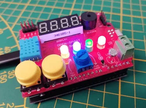
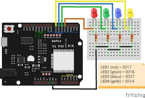
If you don’t have the Rich Shield from Open Smart, you can easily replicate this circuit on a breadboard.
Let’s take a closer look at the source code for generating a PWM signal on an LED:
Step 1 – Importing the Required Modules
To control a GPIO pin and later generate a PWM signal on the ESP32, we need the Pin and PWM modules from machine. We’ll also import the sleep function from time to introduce delays in the code.
# Modules for controlling GPIO pins
from machine import Pin, PWM
# Module for introducing delays in the code
from time import sleep
Step 2 – Initializing a GPIO Pin
In this case, I want to use the red LED1 on the Rich Shield, which is connected to GPIO 17. This pin should be set as an output.
# Initialize a PWM pin
led = PWM(Pin(17, Pin.OUT))
Step 3 – Configuring the PWM Signal
For an LED, setting the frequency to 5 kHz is sufficient.
Setting the PWM frequency to 5 kHz (kilohertz) has several reasons, mainly related to the desired application and the characteristics of the devices being controlled. Here are some key points explaining why 5 kHz can be a good choice:
- Avoiding Flicker in LEDs: At lower PWM frequencies, LEDs can produce flicker that is visible and distracting to the human eye. A frequency of 5 kHz is well above the perception threshold, effectively preventing flicker.
- Efficiency in Motor Control: When controlling DC motors, a higher PWM frequency can lead to smoother and more consistent movement. A frequency of 5 kHz ensures that motors operate more efficiently with less vibration.
- General Compatibility: A frequency of 5 kHz is suitable for many PWM applications, whether for LEDs, motors, or other devices. It offers a good balance between performance and compatibility.
- Avoiding Noise: In some applications, lower frequencies can produce audible noises (e.g., humming in motors or buzzing in speakers). A frequency of 5 kHz is outside the audible range for most people, preventing these noises.
# Set frequency to 5 kHz
led.freq(5000)
Step 4 – Setting the PWM Value
Using the duty function on the PWM object, we set the brightness of the LED. We can input values between 0 and 1023.
# Set brightness to 1/4 (0..1023)
led.duty(256)
Step 5 – Deinitializing the GPIO Pin
Finally, it’s generally a good idea to deactivate the used pins, as otherwise, the connected actuators (LEDs, motors, etc.) will continue to operate. In the case of an LED, it would simply remain lit.
# Deinitialize the pin
led.deinit()
Programming a Fade Effect on an LED
Next, I’d like to show you how to program a fade effect. This effect gradually makes an LED light up and dim down.
For this effect, we start a for-loop ranging from 0 to 1023 and use the index as the brightness value for the LED. It’s important to include a small 15 ms delay so we can actually see the effect.
# Loop from 0 to 1023
for value in range(0, 1024):
    # Set the current value of the index
    # as the brightness level
    led.duty(value)
    # Pause for 15 ms
    sleep(0.015)
Here is the complete code:
# Modules for controlling GPIO pins
from machine import Pin, PWM
# Module for introducing delays in the code
from time import sleep

# Initialize a PWM pin
led = PWM(Pin(17, Pin.OUT))
# Set frequency to 5 kHz
led.freq(5000)

# Loop from 0 to 1023
for value in range(0, 1024):
    # Set the current value of the index
    # as the brightness level
    led.duty(value)
    # Pause for 15 ms
    sleep(0.015)

# Deinitialize the pin
led.deinit()
Controlling LED Brightness with Buttons
On the Rich Shield by Open Smart, you’ll also find two buttons that can be used to control the brightness of the LED. Since adjusting all 1023 levels using buttons would be tedious, I’ll increment and decrement the brightness in steps of 100.
# Modules for controlling GPIO pins
from machine import Pin, PWM
# Module for introducing delays in the code
from time import sleep

# Define variables for the buttons
# Button K1 on GPIO12
k1 = Pin(12, Pin.IN, Pin.PULL_UP)
# Button K2 on GPIO13
k2 = Pin(13, Pin.IN, Pin.PULL_UP)

# Initialize a PWM pin
led = PWM(Pin(17, Pin.OUT))
# Set frequency to 5 kHz
led.freq(5000)

# Variable to store the brightness value
brightness = 0

# Function to set the brightness
def setLEDBrightness():
    global brightness
    # Print the brightness value to the console
    print("Brightness:", brightness)
    # Set the brightness on the LED
    led.duty(brightness)

# Try/Catch block
try:
    # Start an infinite loop
    while True:
        # If button K1 is pressed and brightness is below 1000
        if not k1.value() and brightness < 1000:
            # Increase brightness by 100
            brightness += 100
            # Set the new brightness level
            setLEDBrightness()
            # Pause for 300 ms
            sleep(0.3)

        # If button K2 is pressed and brightness is above 0
        if not k2.value() and brightness > 0:
            # Decrease brightness by 100
            brightness -= 100
            setLEDBrightness()
            # Pause for 300 ms
            sleep(0.3)

# Handle KeyboardInterrupt exception when the program is stopped
except KeyboardInterrupt:
    # Deinitialize the LED
    led.deinit()
Outlook
In the next post, we will explore the rotary potentiometer. I’ll show you how to read its values and use them to control the LEDs.
Letzte Aktualisierung am: 23. January 2025


