A pulse oximeter takes advantage of the blood’s changing properties when carrying oxygen or carbon dioxide around the body. Oxygenated hemoglobin in the red blood cells absorbs more infrared light while letting red light pass through, giving blood its red color. But when carrying carbon dioxide, hemoglobin becomes dark red, so it absorbs more red light while allowing infrared to pass through.

With these properties, it is possible to build a pulse oximeter using an Arduino board and a MAX30100 sensor, which has a red light, infrared LED, and a photodetector. Here’s how to set up the project.
How To Setup the Arduino Pulse Oximeter Project
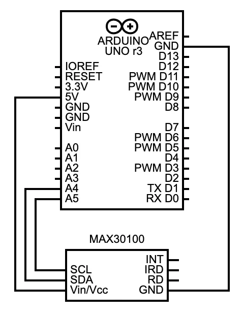
We’ll use an Arduino UNO board with the MAX30100 sensor to set up the pulse oximeter. Make the following connections between the two using jumper wires.
| Arduino UNO | MAX30100 |
|---|---|
| A5 | SCL |
| A4 | SDA |
| GND | GND |
| 5V | Vin/Vcc |
Circuit Diagram
How The Arduino Pulse Oximeter Works
To understand this system, let’s first look at the internal operations of this sensor. It turns on the red and infrared LEDs one at a time, then checks the light that reflects from the patient’s finger using its photodetector. This detection determines the blood oxygen level and heart rate.
For heart rate measuring, the MAX30100 uses these same LEDs and photodetector but in a slightly different way. As the heart pumps oxygenated blood through the arteries and capillaries, it creates bursts of high and low-pressure blood movement where infrared light passes through at different intensities, which can be mapped on a graph. So turning on the infrared LED continuously and detecting its reflection from the finger will create a map where the detected light dips and rises to correspond with the patient’s heart rate.
MAX30100 Technical Specifications
The MAX30100 is a compact and efficient heart rate and pulse oximeter sensor that combines two LEDs, a photodetector, optical elements, and low-noise electronics with ambient light rejection. To better understand how to integrate this sensor into your project, here’s a quick overview of its key technical specifications.
| Feature | Specification |
|---|---|
| Operating Voltage (Chip) | 1.8 V |
| LED Voltage | 3.3 V (each LED) |
| Power Supply Options | Can be powered via 3.3 V or 5 V from Arduino UNO |
| Voltage Regulators Needed | 1.8 V and 3.3 V regulators |
| Temperature Sensor Accuracy | ±1 °C |
| On-Chip Temperature Sensor | Yes, used for calibration |
| FIFO Buffer | Yes, stores up to 16 samples to reduce power usage |
| Interrupt Features | Power ready, Heart rate ready, FIFO almost full, Temperature ready, SpO2 ready |
| INT Pin Usage | Signals data readiness or status via interrupt |
These features make the MAX30100 a powerful choice for health monitoring projects, especially when low power consumption and precise measurements are required. As your project evolves, you can make full use of its advanced capabilities such as interrupts and onboard data buffering.
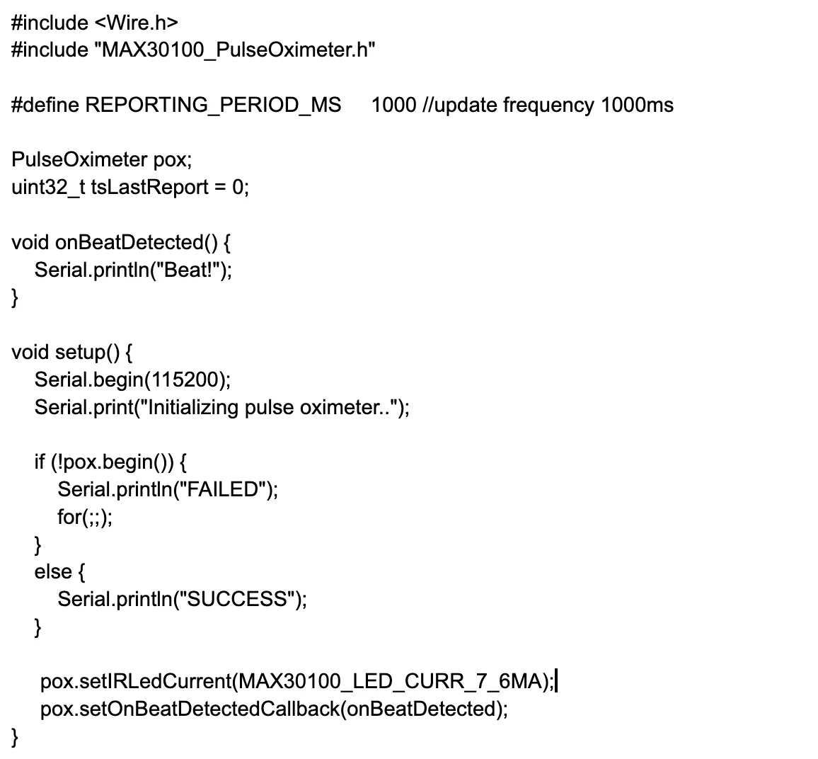
Arduino Code
With the circuit ready, connect the Arduino UNO to your computer, download and install this MAX30100 library to your Arduino IDE, then paste the following code.
How the Code Works
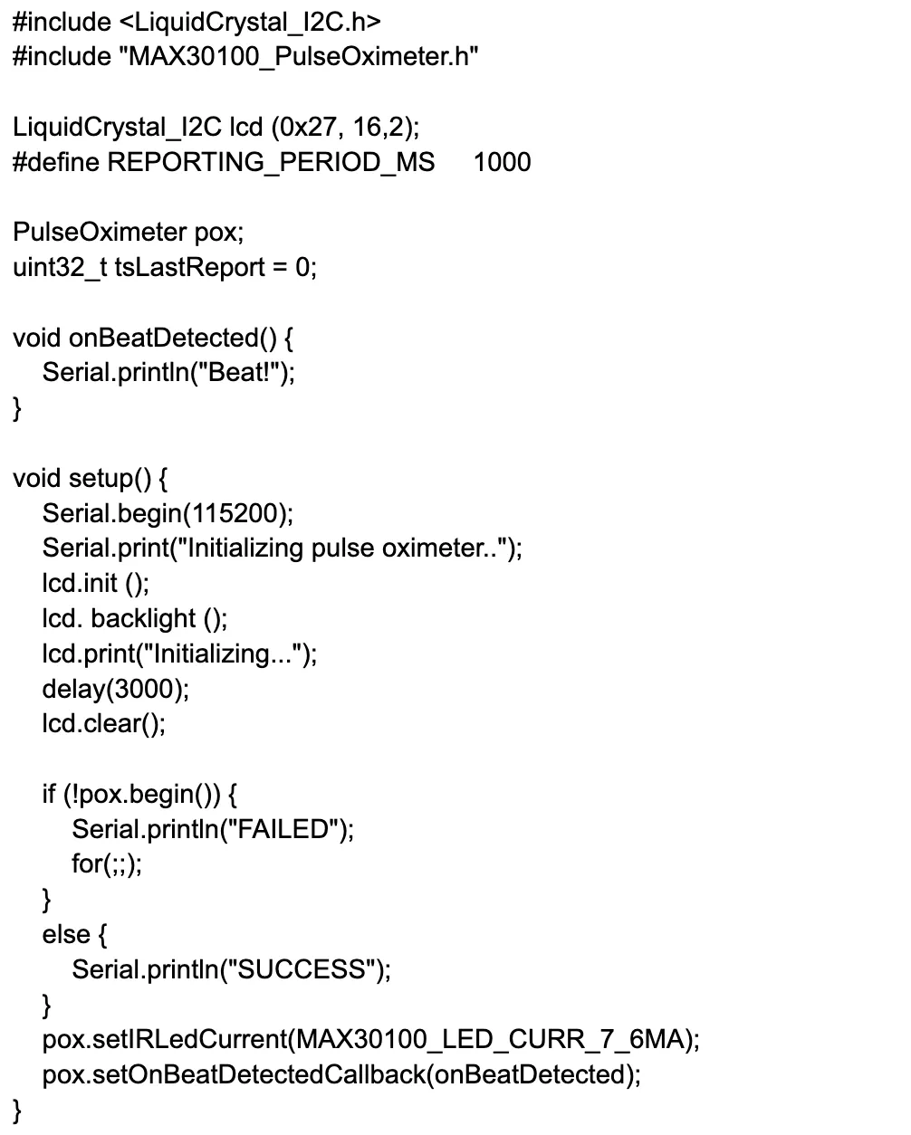
The reporting period refers to the update frequency for collecting the data samples, which is set to one second. Next is the declaration of the pulse meter pox object, which we’ll use in the setup and loop sections, and then the variable for holding the last detected heartbeat. This variable is followed by the “on beat detected function”, which simply displays the word beat when the sensor detects a beat.
In the void setup function, the code prints the initialization message on the screen and then initializes the sensor to detect any errors beforehand. By default, the sensor powers the infrared LEDs using 50mA but this is too high and can cause issues during initialization. So we set the current draw to 7.6mA using the pox object, then register the call back function (on beat detected), which we defined earlier.
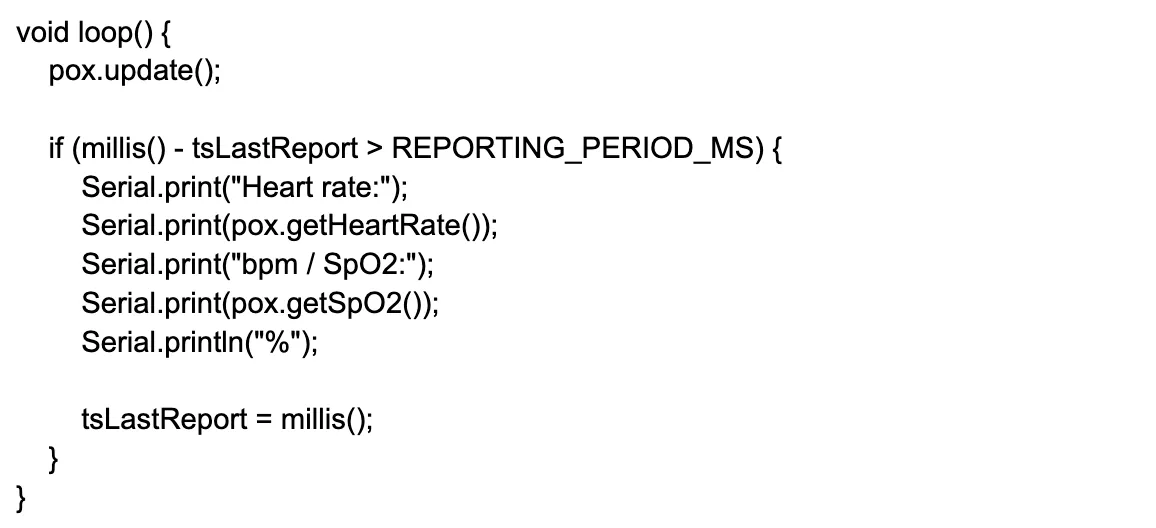
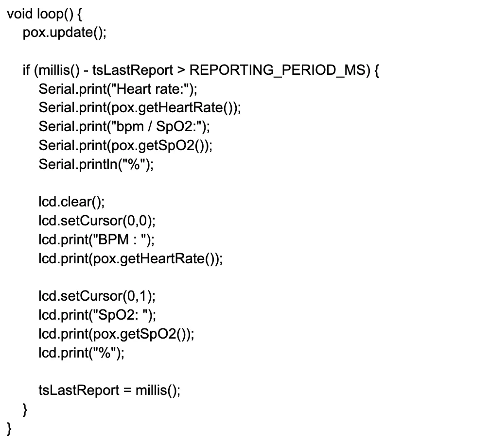
The loop function handles the reading because it runs repetitively. It begins by reading the sensor value using the update function call, while the if function prints the heart rate and oxygen level every second. After that, the last report variable is set to the current time to ensure the loop function runs the if statement again after one second to display the heart rate and oxygen levels as a percentage in real-time.
Some Minor Improvements
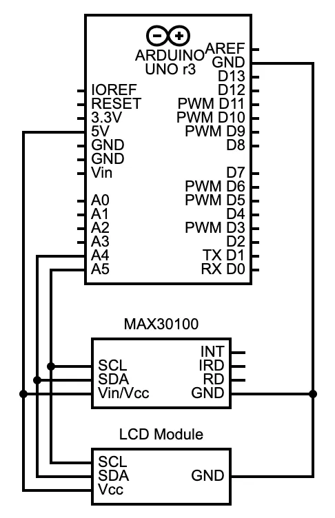
The setup above is all good, but the readings only show or print on the Arduino IDE. What if you want a separate, independent display to view the output? You can introduce an LCD module by connecting it in this setup.
| Arduino UNO | LCD Module (16×2) |
|---|---|
| A5 | SCL |
| A4 | SDA |
| 5V | Vcc |
| GND | GND |
Download and install this liquid crystal library to the IDE, then make these modifications to the code.
How The Code Works
Since the liquid crystal library contains wire.h, there’s no need to include it. So the first modification is to type the LCD object with its address, columns, and rows. The setup function initializes the display (LCD object), turns on its backlight, and shows the text “initializing” for three seconds.
In the loop function, the LCD object clears the screen and then sets the cursor to the top row to print the heart rate from left to right. After that, the cursor moves to the bottom row and prints the oxygen level in the same direction. This happens every second, displaying real-time data from the sensor.
What Next?
Once this prototype is fully functional, the next step is to get a PCB made specifically for this task in a compact form factor. I recommend a medical PCB for this project to ensure maximum reliability in a tiny package. You can check out this PCB manufacturing and assembly service from OurPCB to learn more about the process and benefits you’ll get, plus request a free quote to get an estimate of what you’ll spend.
Final Thoughts
Building an Arduino pulse oximeter is a simple project that you can easily prototype to get to the final product. But to stand out when launching the final product, I recommend making it tiny, which means taking advantage of OurPCB’s medical PCB fabrication and assembly service. Contact them for more details.
Letzte Aktualisierung am: 04. March 2026