In this post, I will show you how to program and read analog sensors using MicroPython on the ESP32 D1 R32. Even if you don’t own the Rich Shield from Open Smart, you can still follow along with the circuits and programs presented here. In the video below, I explain the circuit setup.
In my last video, I demonstrated how to control the brightness of an LED using a PWM signal. I will revisit this example here, as a rotary potentiometer allows for even finer control over the brightness.
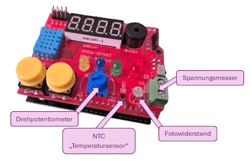
Analog Sensors on the Rich Shield by Open Smart
The Rich Shield from Open Smart includes several analog sensors that we can read and use for small projects:
- rotary potentiometer
- NTC thermistor
- photoresistor
- voltage sensor
Connecting the Sensors to the Shield
The following table shows the pin connections for each sensor:
| Analog Sensor | ESP32 D1 R32 | Arduino UNO R3 |
|---|---|---|
| Rotary Potentiometer | IO02 / ADC12 | A0 |
| NTC Thermistor | IO04 / ADC10 | A1 |
| Photoresistor | IO35 / ADC7 | A2 |
| Voltage Sensor | IO34 / ADC6 | A3 |
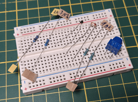
Building the Circuit on a Breadboard
If you don’t own the Rich Shield but still want to follow this tutorial, you can build the circuits as follows:
- Photoresistor
- 10 kΩ photoresistor
- 10 kΩ resistor
- NTC Thermistor
- 100 Ω NTC resistor
- 10 kΩ resistor
- Voltage Sensor / Voltage Divider Circuit
- 30 kΩ resistor
- 7.5 kΩ resistor
For an easier setup, I recommend using preassembled sensor modules. These are inexpensive and have the advantage that you only need to connect a few jumper wires to the microcontroller.
Note: Links marked with an asterisk () are affiliate links. If you make a purchase through these links, I receive a small commission that helps support this blog. The price for you remains the same. Thank you for your support!*
Reading an Analog Sensor with MicroPython
Whether you want to read a rotary potentiometer, an NTC resistor, or a photoresistor, the first step is always reading an analog pin.
For the NTC resistor, you need to apply a mathematical formula to convert the value into a temperature reading.
The other two sensors can be read and used directly.
# Import modules to access GPIOs
from machine import Pin, ADC
# Import module for adding pauses in the code
from time import sleep

# ADC12 on GPIO2, set as input
adc_pin = Pin(2, mode=Pin.IN)
# Initialize an ADC object (Analog-Digital Converter)
adc = ADC(adc_pin)
# Set resolution to 0..1023 (10-bit)
adc.atten(ADC.ATTN_11DB)

# Start infinite loop
while True:
    # Read the current value
    print(adc.read())
    # Pause for 250 ms
    sleep(0.25)
In this example, I use the rotary potentiometer.
Turning it to the right increases the value, while turning it to the left decreases it.
The value range is set to 10-bit, meaning it is limited to 0 to 1023.
Reading the Photoresistor and Controlling LED Brightness
In my last post, I demonstrated how to generate a PWM signal and use it to control an LED’s brightness.
In the following example, I will show you how to read the photoresistor and use it to adjust the LED brightness.
I have inverted the values so that when you place your finger on the sensor and the value decreases, the LED gets brighter.
This program reads the value from the photoresistor and adjusts the LED brightness accordingly.
# Import modules to access GPIOs
from machine import Pin, ADC, PWM
# Import module for adding pauses in the code
from time import sleep

# ADC7 on GPIO35, set as input
adc_pin = Pin(35, mode=Pin.IN)
# Initialize an ADC object (Analog-Digital Converter)
adc = ADC(adc_pin)
# Set resolution to 0..1023 (10-bit)
adc.atten(ADC.ATTN_11DB)
adc.width(ADC.WIDTH_10BIT)

# Red LED on GPIO17, set as output
led1 = PWM(Pin(17, Pin.OUT))
# Set frequency to 5 Hz
led1.freq(5000)

# Start the infinite loop
while True:
    # Read the sensor value
    value = adc.read()
    # Print the value to the command line
    print(value)
    # Set the PWM value
    led1.duty(1023 - value)
    # A short pause of 100 ms
    sleep(0.1)
Programming the Voltage Sensor on the Rich Shield in MicroPython
The Rich Shield includes a built-in voltage sensor, which we can read and use to calculate the voltage with the following code. Unfortunately, there is no documentation available for this sensor, so I am unaware of the exact voltage range.
# Modules for accessing the GPIOs
from machine import Pin, ADC
# Module for accessing functions
# such as inserting a pause in the code
from time import sleep

# Gain factor for signal amplification
GAIN = 1.765

# Reference voltage
# On the ESP32, this is 3.3V
ADC_REF = 3.3

# ADC6 on GPIO34, set as input
adc_pin = Pin(34, mode=Pin.IN)
# Initialize an ADC object
# (Analog-Digital Converter)
adc = ADC(adc_pin)

# Calculate the voltage from the analog value
def calVoltage(sensorValue):
    return sensorValue * ADC_REF / 1023.00 / GAIN

while True:
    # Read the analog value
    sensorValue = adc.read()
    print("Voltage: ", calVoltage(sensorValue)," V", sep=" ")
    sleep(0.5)
With my lab power supply, I was able to read values in a voltage range of 0 to 3 volts. I didn’t want to go any higher to avoid damaging the microcontroller and/or the shield.
Voltage Sensor on the Rich Shield with the ESP32 D1 R32
So far, I have not been able to read the NTC resistor correctly. The values I consistently obtained were about 50% lower than the actual ones. The following code works and provides an approximate value, which, according to my tests, is functional but not entirely correct. At the end of the calculation, the measured value is simply doubled.
# Modules for accessing the GPIOs
from machine import Pin, ADC
# Module for accessing functions
# such as inserting a pause in the code
from time import sleep

from math import log

# ADC10 on GPIO4, set as input
adc_pin = Pin(4, mode=Pin.IN)
# Initialize an ADC object
# (Analog-Digital Converter)
adc = ADC(adc_pin)

# Constants
SAMPLING_RESISTOR = 10000  # Resistance of the reference resistor (10k Ohms)
NTC_R25 = 10000  # Resistance of the NTC resistor at 25°C (10k Ohms)
NTC_B = 3950  # Beta value of the NTC resistor
V_IN = 3.3  # Supply voltage in volts
ADC_MAX = 65535  # Maximum ADC value (for 10-bit ADC)

def get_temperature(adc_value):
    # Calculate the resistance of the NTC resistor
    resistance = (float(adc_value) * SAMPLING_RESISTOR) / (ADC_MAX - adc_value)

    # Calculate the temperature in Kelvin using the Steinhart-Hart equation
    temperature_kelvin = 1 / (log(resistance / NTC_R25) / NTC_B + 1 / 298.15)

    # Convert to Celsius
    temperature_celsius = temperature_kelvin - 273.15
    return temperature_celsius

while True:
    adc_value = adc.read_u16()  # Example ADC value
    print(adc_value)

    print("Temperature: ", get_temperature(adc_value)*2, "°C", sep=" ")
    sleep(0.75)
Outlook
The Rich Shield also includes a piezo buzzer that can generate sounds. Here, we will take a small step back and revisit the topic of “PWM signals on the ESP32.” By the end, you will be able to play a simple melody using the buzzer—so stay tuned!
Letzte Aktualisierung am: 01. February 2025